

Force on a Current-Carrying Conductor in a Magnetic Field: Full Physics Guide
Mastering Fleming’s Left-Hand Rule and Vector Cross Products for NEET, JEE, and Board Exams.

1. Fundamental Concepts & Terminology
To master this topic, you must first understand the three “players” involved in this physical interaction:
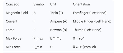
Magnetic Field (B): A region around a magnetic material or a moving electric charge within which the force of magnetism acts. Measured in Teslas (T).
Electric Current (I): The flow of electric charge through a conductor. Measured in Amperes (A).
Conductor Length (L): The specific portion of the wire that resides inside the magnetic field. Measured in Meters (m).
Magnetic Force (F): The mechanical push or pull exerted on the wire due to the interaction of the internal current and the external field. Measured in Newtons (N).
2. Visualizing the Third Dimension
Because physics happens in 3D space, we use specific symbols to represent directions moving toward or away from you:
The Dot (•): Represents a field or current coming OUT of the page (toward your eyes). Think of the tip of an arrow.
The Cross (×): Represents a field or current going INTO the page (away from you). Think of the feathers at the back of an arrow.
3. Determining Direction: Fleming’s Left-Hand Rule
When a current flows perpendicular to a magnetic field, the resulting force is perpendicular to both. To find this direction without complex math, stretch your left hand so the thumb, forefinger, and middle finger are at right angles (90°) to each other:
Forefinger: Points in the direction of the Magnetic Field (B).
Middle Finger: Points in the direction of the Current (I).
Thumb: Points in the direction of the Force (F) or motion.
4. The Mathematical Magnitude
The force is defined by the vector cross product of the length and the magnetic field.
The Vector Equation:
F = I * (L × B)
The Scalar Magnitude:
If there is an angle (θ) between the wire and the field, the strength of the force is:
F = B * I * L * sin(θ)
Maximum Force: Occurs when the wire is perpendicular (90°) to the field (sin(90°) = 1).
Zero Force: Occurs when the wire is parallel (0°) to the field (sin(0°) = 0).
5. 3D Vector Analysis (The Unit Vector Method)
In advanced physics (JEE/NEET level), we use unit vectors i, j, and k to represent the x, y, and z axes.
The Orthogonal Rules:
i × j = k
j × k = i
k × i = j
(Reverse order results in a negative, e.g., j × i = -k)
Worked Example:
Current (I): 10 A
Length (L): 5 meters along the positive x-axis (5i)
Magnetic Field (B): 5 Tesla into the page/negative z-axis (-5k)
Step 1: Calculate (L × B)
5i × (-5k) = -25 * (i × k)
Since (i × k) = -j, the result is: -25 * (-j) = 25j
Step 2: Multiply by Current (I)
F = 10 * 25j = 250j Newtons
Result: The wire experiences a 250 N force in the positive y-direction (Upward).
6. Integration with Mechanics (Net Force & Acceleration)
In the real world, gravity also acts on the wire. To find how the wire actually moves, we calculate the Net Force.
Magnetic Force (Fmagnetic): 250 N (Up)
Weight (W): mass * gravity (e.g., 0.5 kg * 10 m/s² = 5 N Down)
Net Force (F_net): 250 N - 5 N = 245 N (Up)
Calculating Acceleration (a):
Using Newton’s Second Law (F = m * a):
a = Fnet / mass
a = 245 / 0.5 = 490 m/s² upward
7. Summary Table for Quick Revision
NEET Physics: Magnetic Force & Vector Analysis MCQ
Q1. A conductor of length L is placed along the positive x-axis (i) and carries a current I. If the magnetic field B is directed along the positive y-axis (j), what is the direction of the magnetic force F acting on the conductor?
(A) Positive z-axis (k)
(B) Negative z-axis (-k)
(C) Positive y-axis (j)
(D) Negative x-axis (-i)
Q2. What happens to the magnitude of the force F = I * (L × B) if the conductor is placed exactly parallel to the direction of the magnetic field?
(A) The force becomes zero
(B) The force is at its maximum
(C) The force remains unchanged
(D) The force depends only on the current
Q3. According to Fleming’s Left-Hand Rule, which finger must be aligned with the direction of the magnetic field (B)?
(A) Middle finger
(B) Forefinger (Index finger)
(C) Thumb
(D) Ring finger
Q4. In a 3D coordinate system, if a current-carrying wire has a length vector L = 2i and is placed in a magnetic field B = -3k with a current of 2 Amperes, what is the Force vector F? (
A) F = 12j
(B) F = -12j
(C) F = 6k
(D) F = -6i
Q5. A wire of mass 0.2 kg experiences an upward magnetic force of 10 N. Taking g = 10 m/s², what is the net upward acceleration of the wire?
(A) 50 m/s²
(B) 40 m/s²
(C) 10 m/s²
(D) 60 m/s²
Q6. If a magnetic field is represented by dots (•) in a diagram, which direction is the field pointing?
(A) Into the plane of the paper
(B) Out of the plane of the paper
(C) To the right of the paper
(D) Parallel to the conductor
Q7. Applying Newton’s Third Law: If the magnetic field exerts a force on the current-carrying wire, what is the “reaction” force?
(A) There is no reaction because magnetism is a non-contact force (
B) The wire exerts an equal and opposite force on the source of the magnetic field
(C) The wire exerts a force on the ground
(D) The current increases to balance the force
Q8. Calculate the magnitude of force on a 3-meter wire carrying 5 A current in a 2 T field, if the wire is at 30° to the field lines. (Given sin 30° = 0.5)
(A) 30 N
(B) 15 N
(C) 7.5 N
(D) 0 N
Q9. If the direction of the current in the conductor is reversed, what happens to the direction of the magnetic force?
(A) It remains the same
(B) It also reverses (becomes opposite)
(C) It becomes zero
(D) It turns by 90 degrees
Q10. Which physical quantity’s unit vector is represented by “k” in the standard Cartesian coordinate triad?
(A) X-axis
(B) Y-axis
(C) Z-axis
(D) The diagonal axis
Answer Key (For Teacher Reference):
(A) - Rule: i × j = k
(A) - sin(0°) = 0
(B) - Forefinger = B-Field
(A) - 2 * (2i × -3k) = 12j
(B) - (10N - 2N) / 0.2kg = 40
(B) - Dot = Towards observer
(B) - Action-Reaction pair
(B) - 2 * 5 * 3 * 0.5 = 15
(B) - Vector direction flips
(C) - standard i, j, k notation
NEET Reasoning & Assertion Challenge: Circular Loops
Directions: In the following question, a statement of Assertion (A) is followed by a statement of Reason (R). Choose the correct option:
(A) Both A and R are true, and R is the correct explanation of A.
(B) Both A and R are true, but R is NOT the correct explanation of A.
(C) A is true, but R is false.
(D) Both A and R are false.
Assertion (A): For a circular loop of radius R carrying current I placed in the xy-plane, the net magnetic force on the upper semi-circular arc (y > 0) is zero when a uniform magnetic field B is applied along the positive y-axis.
Reason (R): According to Fleming’s Left-Hand Rule, the magnetic force acting on any curved segment of a conductor in a uniform magnetic field must always be directed radially toward the center of curvature.
Correct Option: (D) Both A and R are false.
Detailed Conceptual Breakdown for your Blog:
1. Why Assertion (A) is False:
The Assertion claims the force on the upper arc is zero. This is incorrect.
For the upper arc, the “effective length” vector is a straight line from the left-most point to the right-most point, which is 2R along the positive x-axis (+i).
Since the magnetic field is along the y-axis (+j), the force is calculated as F = I * (2Ri × Bj) = 2IRB k.
Therefore, the upper half experiences a force of magnitude 2IRB directed along the positive z-axis (out of the plane). It is only the total force on the complete closed loop that equals zero.
2. Why Reason (R) is False:
The Reason claims the force is always “radial” (toward the center).
Using Fleming’s Left-Hand Rule or the Cross Product F = I(L × B), we see that the force must be perpendicular to both the current and the magnetic field.
In this specific geometry (loop in xy-plane, field in y-direction), the force is directed along the z-axis.
A radial force would point along the x or y axes. Since the force is along the z-axis (perpendicular to the plane of the loop), it is not radial.
Exam Tip:
Students often confuse “Net Force on a closed loop = 0” with “Force on any part of the loop = 0.” Note that that while the total force is zero in a uniform field, the individual halves experience equal and opposite forces that create a Torque, causing the loop to rotate.