

Refraction at Spherical Surfaces: Formula, Derivation, and Solved Numericals and MCQs
A Complete NEET & JEE Physics Guide to Mastering Curved Interfaces and Hemispherical Glass Surfaces

Watch this Live Class that has complete Theory and Solved Numericals
This guide provides a comprehensive breakdown of the principles, formulas, and strategies for mastering light refraction at curved interfaces, specifically tailored for competitive exams like NEET and JEE.
1. Core Theory: The Physics of Curved Interfaces
Refraction occurs whenever light travels between two media with different Refractive Indices (n). In a curved surface, the boundary is usually spherical or hemispherical.
The Mechanism of Bending:
Angle of Incidence (i) and Angle of Refraction (r) are measured relative to the Normal, which always passes through the Center of Curvature (C).
When moving from a Rarer to Denser medium (e.g., Air to Glass), the ray bends towards the normal.
When moving from a Denser to Rarer medium (e.g., Glass to Air), the ray bends away from the normal.
2. Essential Formulas & Mathematical Tools
a. Refraction at a Spherical Surface
This is the fundamental equation used to find the image position when light travels from one medium into a curved surface of another medium.
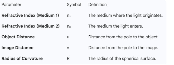
Formula: (μ₂ / v) – (μ₁ / u) = (μ₂ – μ₁) / R
μ₁: Refractive index of the first medium (where the object is).
μ₂: Refractive index of the second medium.
u: Object distance.
v: Image distance.
R: Radius of curvature of the surface.
Note: For refraction from a denser to a rarer medium, the signs in the formula effectively shift to reflect the change in light direction: - (μ₂ / u) + (μ₁ / v) = (μ₁ – μ₂) / R.
b. Lateral Magnification (m)
Magnification tells us how much larger or smaller the image is compared to the object. Unlike mirrors, the formula for refraction at a curved surface includes the refractive indices.
In the study of optics, specifically for refraction at spherical surfaces, magnification describes the relationship between the size of the object and the size of the image formed.
1. Defining the Terms
While often used interchangeably in introductory physics, they specifically refer to the orientation of the image relative to the principal axis:
Lateral (or Transverse) Magnification: This refers to the ratio of the height of the image to the height of the object, measured perpendicular to the principal axis.
Linear Magnification: This is the general term used to describe the factor by which an object’s linear dimensions (height or width) are increased or decreased.
2. The Core Formulas
Height Ratio: M = h₂ / h₁
(Where h₂ is image height and h₁ is object height)
Distance and Index Ratio: Unlike mirrors, magnification in refraction depends on the refractive indices of the two media.
M = (v × n₁) / (u × n₂)
v: Image distance
u: Object distance
n₁ (or μ₁): Refractive index of the medium where the object is placed.
n₂ (or μ₂): Refractive index of the medium the light enters.
The Shortcut (Alternate Form): If the refractive indices are not immediately handy, you can use the radius of curvature (R):
M = (R – v) / (R – u)
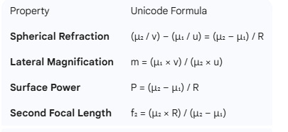
Height-based: m = h₂ / h₁
Index-based: m = (μ₁ × v) / (μ₂ × u)
Alternate Form: m = (R – v) / (R – u)
3. Key Interpretations
Magnitude (|M|): * If |M| > 1, the image is magnified (enlarged).
If |M| < 1, the image is diminished.
If |M| = 1, the image is the same size as the object.
Sign of M: * A positive (+) magnification indicates an erect (upright) image.
A negative (–) magnification indicates an inverted image.
4. Why the Refractive Index Matters
In a mirror, light stays in the same medium, so the speed doesn’t change. In refraction, light changes speed as it moves from n₁ to n₂. This change in speed causes the light rays to bend differently, which is why the magnification formula must “weight” the distances (u and v) by their respective refractive indices.
c. Power and Focal Lengths
The “power” of a surface represents its ability to converge or diverge light rays.
Power (P): P = (μ₂ – μ₁) / R
First Principal Focal Length (f₁): This is the object position for which the image is formed at infinity.
f₁ = –(μ₁ × R) / (μ₂ – μ₁)
Second Principal Focal Length (f₂): This is the image position for an object at infinity.
f₂ = (μ₂ × R) / (μ₂ – μ₁)
Tip: For Power to be in Diopters, R must be in meters.
Tricky Assertion-Reason Question (Optics)
Direction: In the following question, a statement of Assertion (A) is followed by a statement of Reason (R). Choose the correct option from the choices below.
Assertion (A): For a single spherical refracting surface, the first principal focal length (f₁) is always equal in magnitude to the second principal focal length (f₂), regardless of the media on either side.
Reason (R): The power (P) of a refracting surface is defined as P = (μ₂ – μ₁) / R, and since the bending ability is constant for a given surface, the light must converge at the same distance from the pole in both media.
Choices:
(A) Both Assertion (A) and Reason (R) are true, and Reason (R) is the correct explanation of Assertion (A).
(B) Both Assertion (A) and Reason (R) are true, but Reason (R) is NOT the correct explanation of Assertion (A).
(C) Assertion (A) is true, but Reason (R) is false.
(D) Both Assertion (A) and Reason (R) are false.
Answer and Explanation
Correct Answer: (D) Both Assertion (A) and Reason (R) are false.
Why they are False (The “Deep” Concept):
1. Analysis of Assertion (A): The assertion is False. In a single refracting surface, the focal lengths are given by:
f₁ = –(μ₁ × R) / (μ₂ – μ₁)
f₂ = (μ₂ × R) / (μ₂ – μ₁) Since μ₁ (medium 1) and μ₂ (medium 2) are different, the magnitudes |f₁| and |f₂| can never be equal. They are only equal in thin lenses surrounded by the same medium on both sides, but not for a single surface.
2. Analysis of Reason (R): The reason is False. While the formula for Power (P) provided is technically correct, the conclusion that “light must converge at the same distance” is wrong. The relationship between Power and Focal Length for a single surface is:
P = μ₂ / f₂ or P = –μ₁ / f₁ Because the speed of light is different in the two media, the same “bending power” results in different focal distances.
Why this is a trap: Students often memorize that for a lens, f₁ = f₂. They carry this assumption over to a single surface, forgetting that the refractive index of the medium where the focus lies directly scales the focal distance.
d. Quiz: Power and Focal Lengths (Spherical Refraction)
Q1. Which of the following correctly defines the First Principal Focal Length (f₁) for a spherical refracting surface?
A. The image position when the object is at infinity.
B. The object position for which the image is formed at infinity.
C. The distance from the center of curvature to the pole.
D. The point where all incident parallel rays meet after refraction.
Answer: B
Rationale: By definition, the first focal point is the specific object location that results in refracted rays parallel to the principal axis.
Q2. What is the correct expression for the Power (P) of a single spherical refracting surface?
A. P = (μ₂ + μ₁) / R
B. P = (μ₂ – μ₁) / R
C. P = R / (μ₂ – μ₁)
D. P = μ₂ / (μ₁ × R)
Answer: B
Rationale: Power is directly proportional to the difference in refractive indices and inversely proportional to the radius of curvature.
Q3. If a spherical surface has a positive Power (P > 0), how does it affect incident parallel rays?
A. It diverges the rays.
B. It converges the rays.
C. It reflects the rays back into the first medium.
D. The rays pass through without any deviation.
Answer: B
Rationale: In optics, a positive power value signifies a converging action on the incident light.
Q4. To express the Power of a surface in Diopters (D), in what unit must the Radius of Curvature (R) be measured?
A. Centimeters (cm)
B. Millimeters (mm)
C. Meters (m)
D. Inches (in)
Answer: C
Rationale: One Diopter is defined as the reciprocal of one meter (1 m⁻¹).
Q5. What is the relationship between the first focal length (f₁) and the second focal length (f₂)?
A. f₂ / f₁ = –μ₂ / μ₁
B. f₂ / f₁ = μ₂ / μ₁
C. f₁ + f₂ = R
D. f₁ = f₂
Answer: A
Rationale: Dividing the formula for f₂ by f₁ shows that their ratio is the negative ratio of the indices of the media they reside in.
Q6. A glass hemisphere (μ = 1.5) is placed in air (μ = 1). If light travels from air to glass through a convex surface (R = +20 cm), what is the Power?
A. +2.5 D
B. +0.025 D
C. –2.5 D
D. +5.0 D
Answer: A
Rationale: Using P = (1.5 - 1.0) / 0.2 m gives 0.5 / 0.2 = 2.5 D.
Q7. If the refractive index of the first medium (μ₁) is greater than the second (μ₂), and R is positive, the power of the surface will be:
A. Positive
B. Negative
C. Zero
D. Infinite
Answer: B
Rationale: If μ₁ > μ₂, the numerator (μ₂ – μ₁) is negative, leading to a negative power for a positive R.
Q8. The second principal focal length (f₂) for a surface is given by which formula?
A. f₂ = (μ₂ × R) / (μ₂ – μ₁)
B. f₂ = (μ₁ × R) / (μ₂ – μ₁)
C. f₂ = –(μ₂ × R) / (μ₂ – μ₁)
D. f₂ = μ₂ / R
Answer: A
Rationale: f₂ represents the image position in the second medium when the object is at infinity.
Q9. For a plane (flat) refracting surface, what is the value of the Power (P)?
A. P = 1
B. P = Infinity
C. P = 0
D. P = μ₂ – μ₁
Answer: C
Rationale: For a flat surface, R is infinite; any finite number divided by infinity is zero.
Q10. In the formula f₁ = –(μ₁ × R) / (μ₂ – μ₁), why is there a negative sign?
A. Because the first focus is always virtual.
B. To align with the Cartesian sign convention.
C. Because refractive index cannot be negative.
D. It is a mathematical error in the derivation.
Answer: B
Rationale: The negative sign ensures that for a standard converging surface, the focal point is located on the side from which light originates.
4. The “Protection” of Results: Sign Conventions
A single sign error will ruin your calculation. Follow these NEET-Standard rules strictly:
Direction of Light: All distances measured in the direction of the incident light are Positive (+).
Opposite Direction: Distances measured against the direction of incident light are Negative (—).
The Pole (P): All distances must be measured starting from the center of the curved surface (the pole).
Radius (R): If the center of curvature (C) is in the direction of incident light, R is Positive. If it is behind the pole relative to the light, R is Negative.
5. Case Study: Hemispherical Glass Surfaces
In complex problems involving a hemisphere, light often undergoes two refractions:
First Refraction: At the curved glass surface. Use the curved surface formula to find the intermediate image position (v₁).
The Hand-off: The image from the first refraction (v₁) now acts as the virtual object for the second refraction (the flat surface).
Second Refraction: Apply the flat surface refraction rules (where R = infinity) to find the final image position.
6. Key Exam Tips for NEET Aspirants
Identify the Media: Always label which side is n₁ (where the object is) and which is n₂ (where the light goes) before plugging values into the formula.
The “Infinity” Trick: If a question involves a flat surface, remember that R = ∞. In the master formula, (n₂ — n₁) / ∞ becomes zero, simplifying your math.
Draw the Normal: In any ray diagram, always draw a straight line from the Center of Curvature to the point of incidence; this is your Normal.
Unit Conversion: NEET often gives R in cm but asks for Power in Diopters. Convert R to meters immediately!
7. Selection Walla: Quick Practice MCQs
Q1. An object is placed 20 cm in front of a convex glass surface (n = 1.5) of radius 10 cm in air. What is the power of this refracting surface?
(A) 2.5 D
(B) 5.0 D
(C) 10.0 D
(D) 50.0 D
Correct Answer: (B) Explanation: Use the formula P = (n₂ — n₁) / R. Here, n₂ = 1.5, n₁ = 1, and R = 10 cm = 0.1 m. Substituting gives P = (1.5 — 1) / 0.1 = 0.5 / 0.1 = 5.0 D.
Q2. When a light ray enters a medium from a rarer side to a denser side (e.g., from Air to Glass), what is the resulting behavior of the ray?
(A) It bends away from the normal.
(B) It travels straight without any deviation.
(C) It bends towards the normal.
(D) It undergoes Total Internal Reflection back into the rarer medium.
Correct Answer: (C) It bends towards the normal.
Explanation for Students
Change in Speed: According to Snell’s Law, when light moves from a medium of lower refractive index (n₁) to a higher refractive index (n₂), its velocity decreases.
The Normal Rule: To conserve the wave front, the ray must take a shorter path relative to the surface perpendicular, meaning it is “pulled” closer to the Normal.
The Formula Link: This behavior is the physical basis for the sign conventions used in our master formula: (n₂ / v) – (n₁ / u) = (n₂ – n₁) / R.
Selection Walla Pro-Tip: In exams, if you are confused, remember the acronym TAG (Towards Air-to-Glass) or F.A.S.T. (Fast to Slow, Towards the normal)..
Correct Answer: (C) Explanation: According to Snell’s Law and curved surface geometry, rays moving into a denser medium slow down and are pulled toward the normal. This is a fundamental principle used to derive the curved surface formula.
Q3. If the magnification (M) of an image formed by a curved surface is —2.0, what does this tell you about the image?
(A) It is real and erect.
(B) It is virtual and diminished.
(C) It is real and inverted.
(D) It is virtual and erect.
Correct Answer: (C) Explanation: A negative magnification sign indicates that the image is inverted relative to the object. In single refracting surfaces, inverted images formed on the opposite side are real.
8. Advanced Bullet-Point Notes Summary
Introduction & Basics
Curved surface separates two media with different refractive indices; light refracts accordingly.
Key parameters: object distance (u), image distance (v), refractive indices (n₁, n₂), radius of curvature ®.
Angles of incidence and refraction follow Snell’s Law.
Derivation and Formulae
Derivation and Formulae
Relationship: (n₂ / v) – (n₁ / u) = (n₂ – n₁) / R
(Curved surface formula)
Magnification: Related to object/image heights and refractive indices:
M = (v × n₁) / (u × n₂)
Sign Convention: Adjust formula signs based on the direction of light travel (rarer to denser or vice versa).
Adjust formula signs based on the direction (rarer to denser or vice versa).
Refraction Direction and Adjustments
For object inside denser medium, formula signs change.
First and second principal focal lengths are focal points for converging/diverging rays.
Power of surface = reciprocal of focal length, indicating converging/diverging ability.
Diagrammatic Approach
Draw normals at incidence points on curved surfaces.
Trace incident and refracted rays applying Snell’s law; use dotted lines for virtual rays.
Diagrams clarify image formation and position.
Case Study: Hemispherical Surface (See the Numerical solved below)
Object in air, rays refract twice: curved glass-air interface and flat glass-air interface.
Calculate intermediate image after first refraction; treat it as object for second refraction.
Careful application of sign conventions essential for correct final image position.
Sign Conventions & Problem Solving
Positive distances along incident ray direction; negative otherwise.
Radius sign depends on center of curvature relative to incident light.
Consistency in sign use avoids errors in calculations.
Exam Application & Practice
NEET questions focus on applying formulas and understanding refraction scenarios.
Calculate magnification, power, and focal lengths accurately.
Practice multiple problems; use diagrams alongside formulas for clarity.
Conclusion
Mastery of curved surface refraction formulas and sign conventions critical in optics.
Diagrammatic understanding complements formula application.
Logical reasoning and regular practice essential for success in optics problems.
9 . Summary of Problem-Solving Strategy
Step 1: Identify the media on either side of the curved surface; note refractive indices μ₁ and μ₂.
Step 2: Determine whether light is refracted from denser to rarer or vice versa.
Step 3: Apply the curved surface refraction formula
Step 4: Calculate magnification
Step 5: For multiple surfaces (e.g., hemispheres), apply formulas sequentially, treating the image from the first surface as the object for the second.
Step 6: Draw ray diagrams accurately, marking normals and angles, to visualize refraction and image formation.
Step 7: Use focal length and power formulas to analyze lens-like behavior of curved refracting surfaces.
Step 8: Cross-verify results by checking physical feasibility of image position (real/virtual) and magnification sign.
10. Key Takeaways
Understanding refraction at curved surfaces requires careful attention to sign conventions and refractive index relations.
Memorizing the core formulas for refraction, magnification, and focal length is critical for exam success.
Two-surface refraction problems need stepwise application of formulas and careful interpretation of intermediate images.
Diagrammatic analysis enhances conceptual clarity and aids problem-solving.
Power of curved refracting surfaces links optical properties to focal lengths, helping in lens design understanding
11. Refraction through a Glass Hemisphere
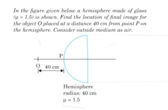
Question: In the figure provided, a hemisphere made of glass (refractive index μ = 1.5) is shown. Find the location of the final image for an object O placed at a distance of 40 cm from point P on the curved surface. Assume the surrounding medium is air (μ = 1). The radius of the hemisphere is 40 cm.
Solution
To find the final position, we must track the light through two distinct boundaries: the curved surface and the flat surface.
Step 1: Refraction at the Curved Surface
We use the formula for refraction at a spherical surface:
(μ₂ / v₁) – (μ₁ / u) = (μ₂ – μ₁) / R
Given values:
μ₁ (Air) = 1
μ₂ (Glass) = 1.5
u = –40 cm (Object is to the left of P)
R = +40 cm (Center of curvature is to the right of P)
Calculation: (1.5 / v₁) – (1 / –40) = (1.5 – 1) / 40
(1.5 / v₁) + (1 / 40) = 0.5 / 40 1.5 / v₁ = (0.5 / 40) – (1 / 40)
1.5 / v₁ = –0.5 / 40
1.5 / v₁ = –1 / 80
v₁ = –120 cm
The first surface creates a virtual image (I₁) located 120 cm to the left of point P.
Step 2: Refraction at the Flat Surface
Now, the image I₁ acts as a virtual object for the second (flat) surface.
Distance from the flat surface: The flat surface is located at a distance equal to the radius (R = 40 cm) from point P. Since I₁ is 120 cm to the left of P, its distance from the flat surface (u₂) is: u₂ = –(120 + 40) = –160 cm
For a flat surface, the radius of curvature R = ∞. The formula simplifies to: (μ₃ / v_final) – (μ₂ / u₂) = 0 (where μ₃ is the air on the exit side)
Calculation: (1 / v_final) – (1.5 / –160) = 0
1 / v_final = –1.5 / 160
1 / v_final = –15 / 1600
v_final = –1600 / 15
v_final = –106.67 cm
Final Result
The final image is formed at a distance of 106.67 cm to the left of the flat surface.
Since the flat surface is 40 cm from P, the final image is 66.67 cm to the left of point P.